Week 12 Molding and casting
Group assignment
Find the link to group assignmentt here
Individual assignment
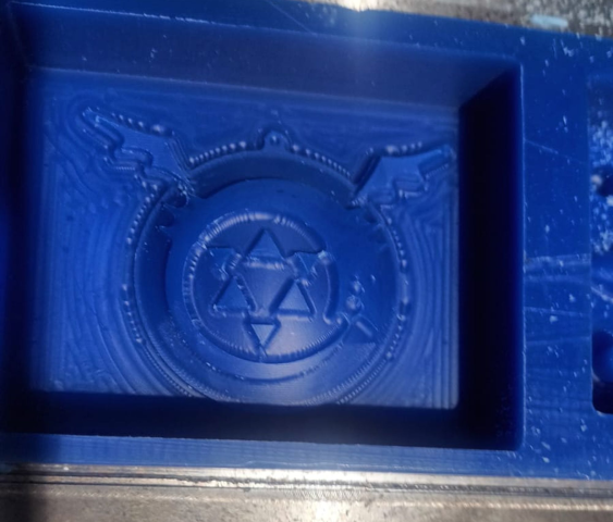
I decided to do this anime symbol as a badge/Keychain. My initial design was 2D and I was told that it doesn’t qualify for 3D milling.
.png)
So I made it into a curved surface
.png)
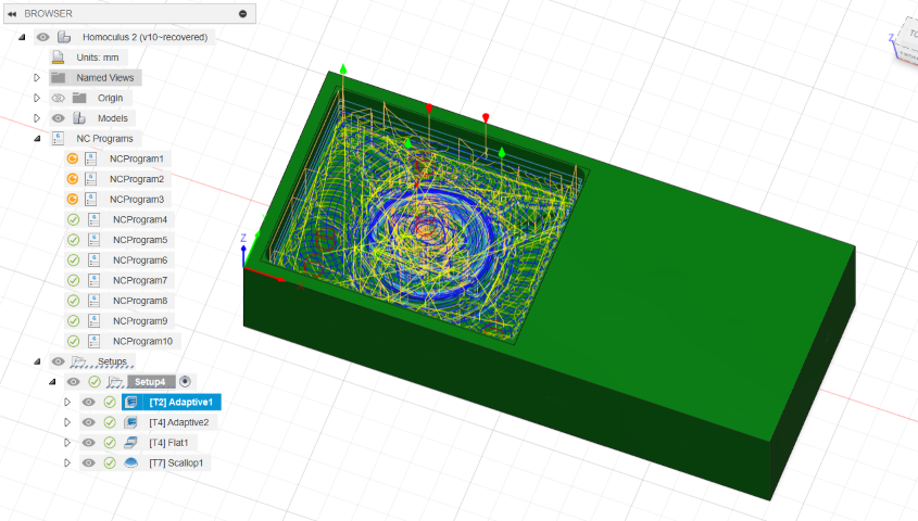
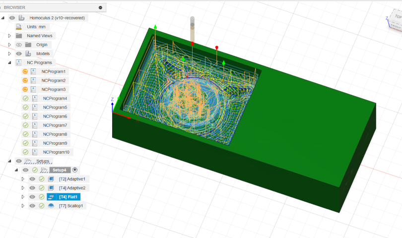
CAM
Computer-Aided Manufacturing (CAM) in Fusion 360 refers to the process of using computer software to control and automate the manufacturing of parts and components. This involves converting a digital design or model into instructions that can be executed by machines such as CNC (Computer Numerical Control) mills, lathes, or 3D printers. CAM software helps streamline the manufacturing process by generating toolpaths, optimizing cutting strategies, and simulating machining operations to ensure accuracy and efficiency in production. In Fusion 360, CAM capabilities are integrated with CAD (Computer-Aided Design) functionalities, allowing users to seamlessly transition from designing to manufacturing within the same software environment.
Tool strategies
Adaptive clearing
Adaptive clearing is a machining strategy used in Fusion 360's CAM environment. It's designed to efficiently remove material from a workpiece while maintaining consistent cutting forces and maximizing tool life. Here's a brief explanation of how adaptive clearing works:
- Optimized Toolpath: Adaptive clearing generates an optimized toolpath that removes material in a series of overlapping passes. This strategy helps to avoid sudden changes in cutting forces and minimizes tool wear.
- Constant Engagement: The tool engagement in adaptive clearing remains relatively constant throughout the operation. This means that the tool maintains a consistent load, which can lead to smoother cuts and reduced vibrations.
- Variable Stepover: Adaptive clearing adjusts the stepover distance dynamically based on the geometry of the part and the cutting conditions. This flexibility allows for efficient material removal while avoiding excessive tool deflection.
- Trochoidal Motion: The tool motion in adaptive clearing often follows a trochoidal pattern, which involves circular or curved movements. This motion helps to distribute wear on the tool more evenly and can improve surface finish.
Flat
Tool used: 3mm flat end mill
The flat tool strategy in Fusion 360's CAM refers to a machining approach that uses flat-bottomed tools, such as end mills or face mills, to remove material from a workpiece. Here's a brief overview of the flat tool strategy:
- Tool Selection: Flat tool strategies involve using tools with flat cutting surfaces, typically end mills with flat bottoms. These tools are suitable for a wide range of machining operations, including facing, contouring, slotting, and pocketing.
- Cutting Parameters: When setting up a flat tool strategy in Fusion 360, you'll specify cutting parameters such as feeds, speeds, depths of cut, and stepovers. These parameters determine how the tool engages with the material and how much material is removed in each pass.
- Toolpaths: Fusion 360 generates toolpaths based on the selected flat tool strategy. These toolpaths guide the tool's movement across the workpiece to remove material efficiently and accurately. Common toolpath types include facing (for flat surfaces), contouring (for outlining shapes), pocketing (for removing material from enclosed areas), and slotting (for cutting narrow slots).
- Optimization: Fusion 360's CAM environment allows for optimization of toolpaths to achieve desired machining results. This may include adjusting cutting strategies, optimizing toolpath entry and exit points, and minimizing tool changes for increased efficiency.
Overall, the flat tool strategy in Fusion 360 is versatile and effective for a variety of milling operations, providing users with the tools and flexibility needed to produce precise and high-quality machined parts.
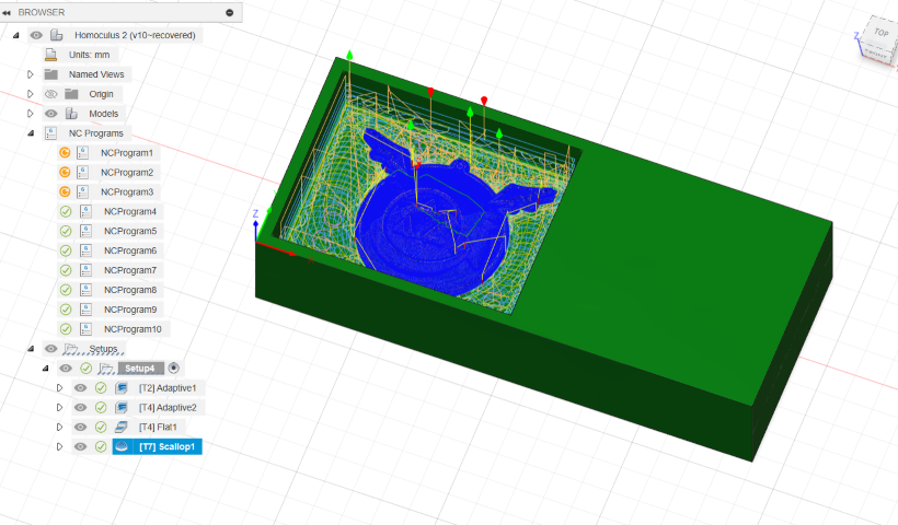
Scallop
The scallop toolpath strategy in Fusion 360's CAM is used for finishing operations to achieve a smooth surface finish on machined parts. Here's a brief explanation of the scallop tool strategy:
- Purpose: The scallop toolpath is designed to remove minimal material in each pass, leaving behind a series of scallop-like marks. This strategy is commonly used for finishing surfaces to achieve a high-quality, smooth finish.
- Tool Selection: The tool used for scallop toolpaths is typically a ball-end mill or a similar tool with a rounded cutting edge. This tool geometry allows for smooth, curved cuts that help reduce visible tool marks on the finished surface.
- Cutting Parameters: When setting up a scallop tool strategy in Fusion 360, you'll specify cutting parameters such as stepovers, feeds, speeds, and depths of cut. The stepover distance determines the spacing between toolpath passes and influences the final surface finish.
- Toolpaths: Fusion 360 generates toolpaths based on the scallop tool strategy, guiding the tool's movement across the workpiece in a series of overlapping passes. The toolpath is calculated to minimize tool marks and achieve a consistent scallop pattern across the surface.
- Surface Finish: The scallop toolpath strategy aims to produce a uniform surface finish with minimal visible tool marks. By controlling the stepover distance and tool engagement, users can achieve the desired level of surface smoothness and quality.
Overall, the scallop tool strategy in Fusion 360 is an effective method for finishing machined parts, particularly curved or contoured surfaces, to achieve a high-quality surface finish suitable for various engineering and manufacturing applications.
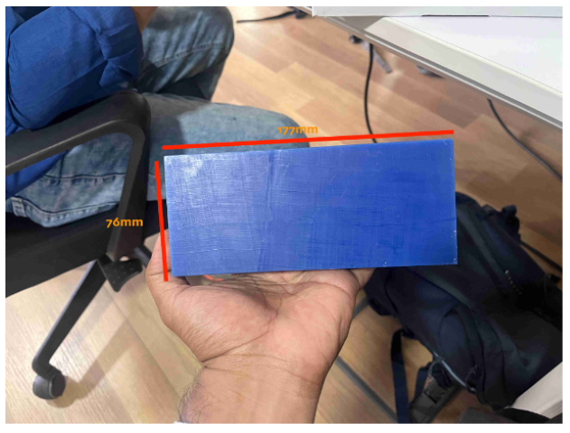
Milling
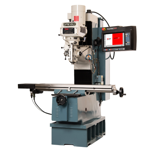
DPM RX2 Vertical Milling Machine
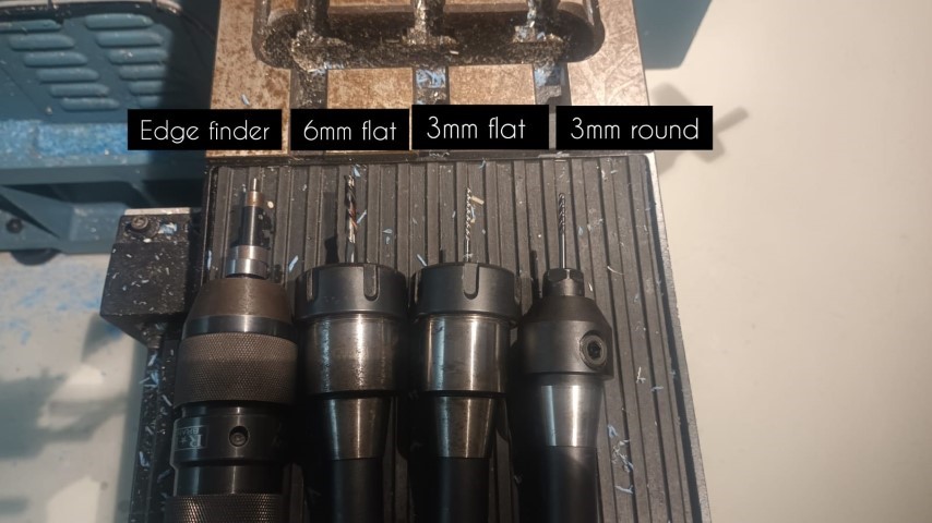
Tools used
Setting up the offset
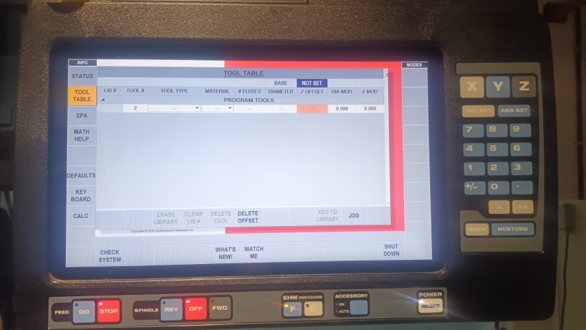
Setting the offset in a DPM RX2 Vertical Milling Machine typically involves adjusting the workpiece or tool position relative to the machine's reference point. Here's a general guide on how to set offsets on such a machine:
- Machine Initialization: Start by ensuring that the DPM RX2 Vertical Milling Machine is properly initialized and that all necessary safety precautions are in place.
- Workpiece Setup: Securely clamp the workpiece to the machine table using appropriate fixtures or clamps. Ensure that the workpiece is positioned accurately and securely to prevent movement during machining.
- Tool Setup: Install the desired cutting tool into the machine spindle. Make sure the tool is securely tightened and aligned properly with the workpiece.
- Reference Point: Identify the machine's reference point, which is typically set as the origin (0,0,0) for the machining coordinates. This reference point serves as the starting position for tool movements and offsets.
- Offset Adjustment: Use the machine's control panel or software interface to adjust tool offsets as needed. This may involve entering offset values for tool length, tool diameter, or workpiece position in relation to the reference point.
- Testing and Verification: Before starting the machining operation, perform a test run or toolpath simulation to verify that the offsets are set correctly. Check for any collisions or inaccuracies in tool movements.
- Fine-Tuning: If necessary, fine-tune the offsets based on the machining results and any dimensional adjustments required for the workpiece.
- Machining Operation: Once the offsets are properly set and verified, proceed with the machining operation according to the desired toolpaths and cutting parameters.
It's important to consult the DPM RX2 Vertical Milling Machine's user manual or operating instructions for specific details on setting offsets and using the machine's control interface, as different machines may have variations in their offset adjustment procedures.
Tracking
Once everything is set we can manually run the milling and see if the tool is working properly
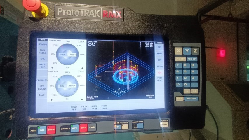
When you are sure it’s working just like the tool simulation click on “CNC RUN’
.jpeg)
We can choose to see the toolpath simulation on the screen
.jpeg)
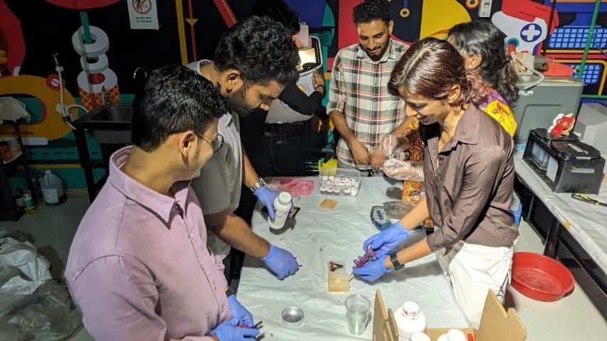
Molding
For creating the mold, we used Adithya Silicone Rubber RTV
It is specified that we should use 30 ml hardener for 1kg of silicone. if we don’t add enough hardener the silicon won’t form a proper mold.
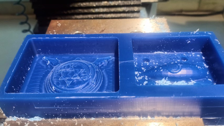
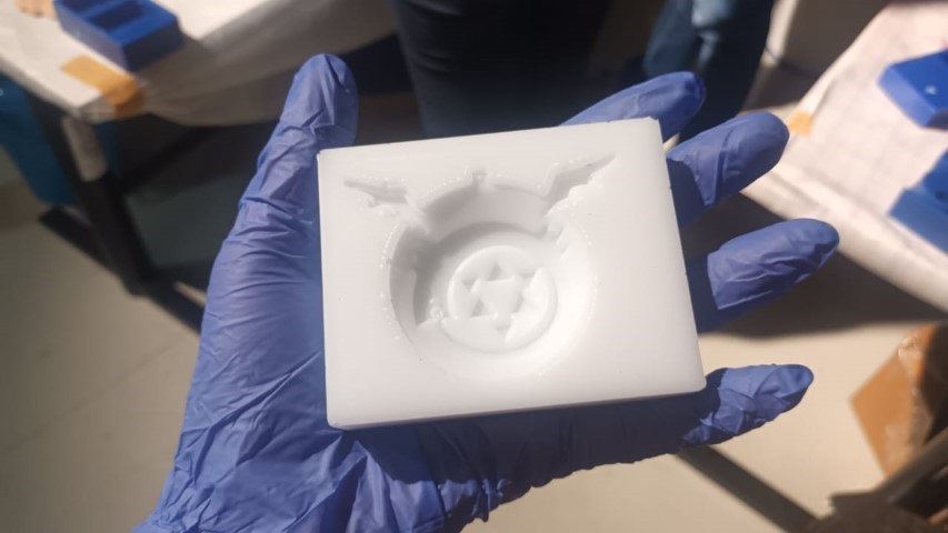
After almost 24 hours I took out the mold and it had come out properly
Casting
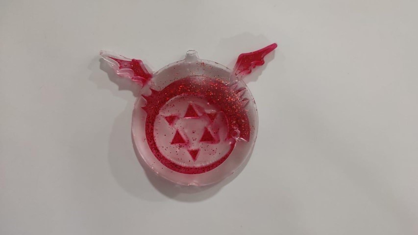
I wanted to highlight the symbol by mixing red dye in resin
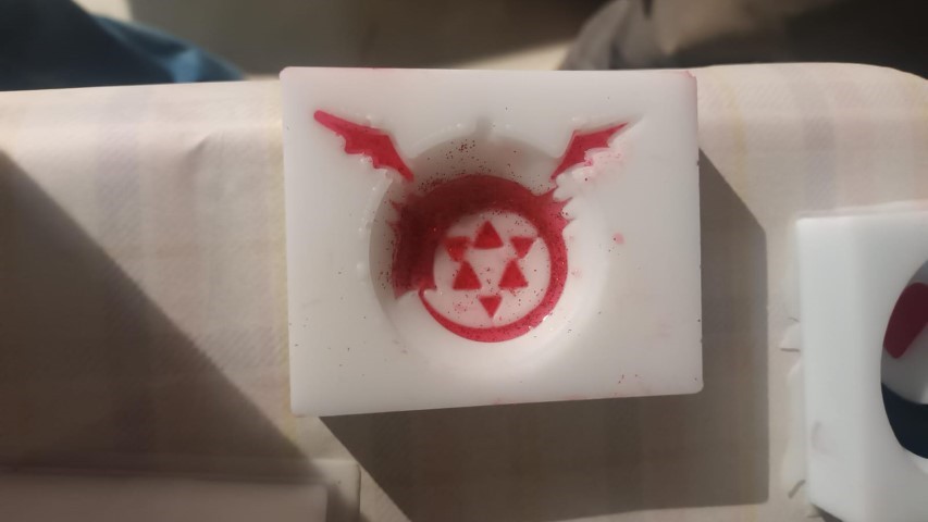
Then after around an hour I poured the transparent resin
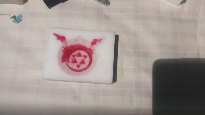
Final Result